
- Georges Sagnac: L'ether lumineux demontre par l'effet du vent relatif d'ether dans un interferometre en rotation uniforme, in: Comptes Rendus 157 (1913), S. 708-710
- Georges Sagnac: Sur la preuve de la réalité de l'éther lumineux par l'expérience de l'interférographe tournant, in: Comptes Rendus 157 (1913), S. 1410-1413
- Albert Abraham Michelson, Henry G. Gale: The Effect of the Earth's Rotation on the Velocity of Light, in: The Astrophysical Journal 61 (1925), S. 140-145
- H. Ives, JOSA 28, pp.296-299 (1938)
.
Sagnac effect
The Sagnac effect (also called Sagnac Interference), named after French physicist Georges Sagnac, is a phenomenon encountered in interferometry that is elicited by rotation. The Sagnac effect manifests itself in a setup called ring interferometry. A beam of light is split and the two beams are made to follow a trajectory in opposite directions. To act as a ring the trajectory must enclose an area. On return to the point of entry the light is allowed to exit the apparatus in such a way that an interference pattern is obtained. The position of the interference fringes is dependent on the angular velocity of the setup. This arrangement is also called a Sagnac interferometer.
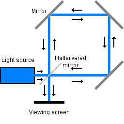
Schematic representation of a Sagnac interferometer.
Usually several mirrors are used, so that the lightbeams follow a triangular or square trajectory. Fiber optics can also be employed to guide the light. The ring interferometer is located on a platform that can rotate. When the platform is rotating the lines of the interference pattern are displaced as compared to the position of the interference pattern when the platform is not rotating. The amount of displacement is proportional to the angular velocity of the rotating platform. The axis of rotation does not have to be inside the enclosed area.
When the platform is rotating, the point of entry/exit moves during the transit time of the light. So one beam has covered less distance than the other beam. This creates the shift in the interference pattern. Therefore, the interference pattern obtained at each angular velocity of the platform features a different phase-shift particular to that angular velocity.
In the above discussion, the rotation mentioned is rotation with respect to an inertial reference frame. Since this experiment does not involve a relativistic velocity, the same wording is valid both in the context of classical electrodynamics and special relativity.
The Sagnac effect is the electromagnetic counterpart of the mechanics of rotation. A gimbal mounted gyroscope remains pointing in the same direction after spinning up, and thus can be used as the reference for an inertial guidance system. A Sagnac interferometer measures its own angular velocity with respect to the local inertial frame; hence just as a gyroscope it can provide the reference for an inertial guidance system.
Interferometry with Ring lasers
The type of ring interferometer that was described in the opening section is sometimes called a 'passive ring interferometer'. A passive ring interferometer uses light entering the setup from outside. The interference pattern that is obtained is a fringe pattern, and what is measured is a phase shift.
It is also possible to construct a ring interferometer that is self-contained, based on a completely different arrangement. The light is generated and sustained by incorporating laser excitation at some point in the ring-shaped path of the light. The ring-shaped laser cavity is enclosed, and the lasing medium must not come in contact with outside air. This setup is called a ring laser.
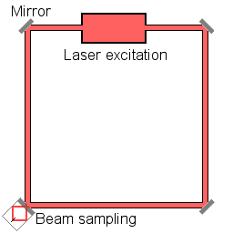
Schematic representation of a ring laser setup. At the beam sampling location, a fraction of each of the counterpropagating beams exits the laser cavity. (*)
The red and blue dots represent counter-propagating photons, the grey dots represent molecules in the laser cavity. (*)
To understand what happens in a ring laser cavity, it is helpful to discuss the physics of the laser process in a laser setup with continuous generation of light. As the laser excitation is started, the atoms or molecules inside the cavity emit photons, but since the atoms have a thermal velocity, the light inside the laser cavity is at first a range of frequencies, corresponding to the statistical distribution of velocities. The process of stimulated emission makes one frequency quickly outcompete other frequencies, and after that the light is extremely close to monochromatic.
When a ring laser is rotating, the laser process generates two frequencies of laser light.
In every section of the ring laser cavity, the light propagates with the same velocity in either direction. For the sake of simplicity, assume that all emitted photons are emitted in a direction parallel to the ring. (That is in fact a huge simplification, but it does not affect the content of this exposition.) The atoms in the laser cavity, represented as grey dots in the animation, have a thermal velocity, and on average they have a velocity in counter-clockwise direction along the ring. The molecules in the laser cavity can be seen as resonators. A passing photon will stimulate emission of the excited molecule only if the frequency of the passing photon exactly matches the frequency of the photon that the molecule is ready to emit.
A photon that is emitted in counter-clockwise direction is on average Doppler-shifted to a higher frequency, a photon that is emitted in clockwise direction is on average Doppler-shifted to a lower frequency. The upwards Doppler-shifted photons are more likely to stimulate emission on interaction with molecules that they "catch up with", the downwards shifted photons are more likely to stimulate emission on interaction with molecules that they meet "head on". Seen in this way, the fact that the ring laser generates two frequencies of laserlight is a direct consequence of the fact that everywhere along the ring the velocity of light is the same in both directions. The constancy of the speed of light acts as a constant background, and the molecules inside the laser cavity have a certain velocity with respect to that background. This constant background is referred to as inertial space.
The laser light that is generated is sampled by causing a fraction of the light to exit the laser cavity. By bringing the two frequencies of laserlight to interference a beat frequency is obtained; the beat frequency is the difference between the two frequencies. This beat frequency can be thought of as an interference pattern in time. (The more familiar interference fringes of interferometry are a spatial pattern). The period of this beat frequency is linearly proportional to the angular velocity of the ring laser with respect to inertial space.
In the case of ring laser interferometry there is no need for calibration. (In a sense one might say that the process is self-calibrating). The beat frequency will be zero if and only if the ring laser setup is non-rotating with respect to inertial space.
Lock-in
Because of the way the laser light is generated, light in laser cavities has a strong tendency to be monochromatic (and usually that is precisely what laser apparatus designers want). This tendency to not split in two frequencies is called 'lock-in'. The ring laser devices incorporated in navigational instruments (to serve as a ring laser gyroscope) are generally too small to go out of lock spontaneously. By "dithering" the gyro through a small angle at a high audio frequency rate, going out of lock is ensured.
Synchronization procedures
The procedures for synchronizing clocks all over the globe must take the rotation of the Earth into account. The signals used for the synchronizing procedure can be in the form of electric pulses conducted in electric wires, they can be light pulses conducted in fiber optic cables, or they can be radio signals.
The red and blue dots represent counter-propagating signals, the grey dots represent stations along the way.
If a number of stations situated on the equator relay pulses to one another, will the time-keeping still match after the relay has circumnavigated the globe? One condition for handling the relay correctly is that the time it takes the signal to travel from one station to the next is taken into account each time. On a non-rotating planet that ensures fidelity: two time-disseminating relays, going full circle in opposite directions around the globe, will arrive at the originating station simultaneously. However, on a rotating planet, it must also be taken into account that the receiver moves during the transit time of the signal, shortening or lengthening the transit time compared to what it would be in the situation of a non-rotating planet.
It is recognized that the synchronization of clocks and ring interferometry are related in a fundamental way. Therefore the necessity to take the rotation of the Earth into account in synchronization procedures is also called the Sagnac effect.
History of the Sagnac Effect
The first ring interferometry experiment aimed at observing the correlation of angular velocity and phase-shift was performed by the Frenchman Georges Sagnac in 1913, which is why the effect is named for him. Its purpose was to detect "the effect of the relative motion of the ether". An experiment conducted in 1911 by Francis Harress, aimed at making measurements of Fresnel drag of light propagating through moving glass, was later recognized as actually constituting a Sagnac experiment. Harress had ascribed the "unexpected bias" to something else.
In 1926 a very ambitious ring interferometry experiment was set up by Albert Michelson and Henry Gale. The aim was to find out whether the rotation of the Earth has an effect on the propagation of light in the vicinity of the Earth. The Michelson-Gale experiment was a very large ring interferometer, (a perimeter of 1.9 kilometer), large enough to detect the angular velocity of the Earth. The outcome of the experiment was that the angular velocity of the Earth as measured by astronomy was confirmed to within measuring accuracy. The ring interferometer of the Michelson-Gale experiment was not calibrated by comparison with an outside reference (which was not possible, because the setup was fixed to the Earth). From its design it could be deduced where the central interference fringe ought to be if there would be zero shift. The measured shift was 230 parts in 1000, with an accuracy of 5 parts in 1000. The predicted shift was 237 parts in 1000.
Calculations
The Sagnac effect is not an artifact of the choice of reference frame. It is independent of the choice of reference frame, as is shown by a calculation that invokes the metric tensor for an observer at the axis of rotation of the ring interferometer and rotating with it yielding the same outcome. If one starts with the Minkowski metric and does the coordinate conversions ![]() and
and ![]() , the line element of the resultant metric is
, the line element of the resultant metric is
![]()
where
* t is proper time for the central observer,
* r is distance from the center,
* θ is the angular distance along the ring from the direction the central observer is facing,
* z is the direction perpendicular to the plane of the ring, and
* ω is the rate of rotation of the ring and the observer.
Under this metric, the speed of light tangent to the ring is ![]() depending on whether the light is moving against or with the rotation of the ring. Note that only the case of ω = 0 is inertial. For
depending on whether the light is moving against or with the rotation of the ring. Note that only the case of ω = 0 is inertial. For ![]() this frame of reference is non-inertial, which is why the speed of light at positions distant from the observer (at r = 0) can vary from c.
this frame of reference is non-inertial, which is why the speed of light at positions distant from the observer (at r = 0) can vary from c.
Practical uses of the Sagnac Effect
The Sagnac Effect is employed in current technology. One use is in inertial guidance systems. Ring interferometers are extremely sensitive to rotations, which need to be accounted for if an inertial guidance system is to return correct results.
The Global Positioning System needs to take the rotation of the Earth into account in the procedures of using radio signals to synchronize clocks.
See also
* Born coordinates
* Fibre optic gyroscope
References
Retrieved from "http://en.wikipedia.org/"
All text is available under the terms of the GNU Free Documentation License
