
- Electron Multiplier Simulation of electron multiplier tube
- Molecular expressions A java simulation and tutorial on photomultiplier tubes
- Photomultiplier Tubes Basics and Applications from Hamamatsu Photonics
- Photomultiplier Handbook (4MB PDF) from Burle Industries, essentially the Engstrom-RCA Handbook reprinted
- Photomultiplier Technical Papers from Electron Tubes Ltd
- Photomultiplier Tubes: Principles and Applications, a reference book from PHOTONIS.
.
Photomultiplier
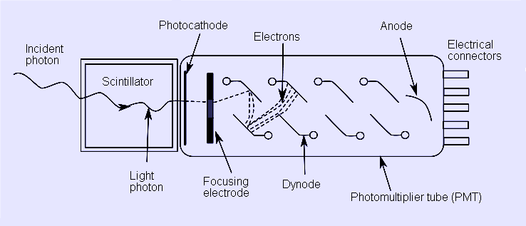
Schematic of a photomultiplier tube coupled to a scintillator.
Photomultiplier tubes (photomultipliers or PMTs for short) are extremely sensitive detectors of light in the ultraviolet, visible and near infrared. These detectors multiply the signal produced by incident light by as much as 108, from which single photons can be resolved. The combination of high gain, low noise, high frequency response and large area of collection have meant that these devices still find applications in nuclear and particle physics, astronomy, medical imaging and motion picture film scanning (telecine). Semiconductor devices like avalanche photodiodes have replaced photomultipliers in some applications, but photomultipliers are still used in most cases.
Photomultipliers are constructed from a glass vacuum tube which houses a photocathode, several dynodes, and an anode. Incident photons strike the photocathode material which is present as a thin deposit on the entry window of the device, with electrons being produced as a consequence of the photoelectric effect. These electrons are directed by the focusing electrode towards the electron multiplier, where electrons are multiplied by the process of secondary emission.
The electron multiplier consists of a number of electrodes, called dynodes. Each dynode is held at a more positive voltage than the previous one. The electrons leave the photocathode, having the energy of the incoming photon (minus the work function of the photocathode). As they move towards the first dynode they are accelerated by the electric field and arrive with much greater energy. On striking the first dynode, more low energy electrons are emitted and these, in turn, are accelerated toward the second dynode. The geometry of the dynode chain is such that a cascade occurs with an ever-increasing number of electrons being produced at each stage. Finally the anode is reached where the accumulation of charge results in a sharp current pulse indicating the arrival of a photon at the photocathode.
Usage considerations
Photomultiplier tubes typically require 1000 to 2000 volts for proper operation. The most negative voltage is connected to the cathode, and the most positive voltage is connected to the anode. (Negative high voltage supplies are usually preferred.) Voltages are distributed to the dynodes by a resistive voltage divider, though variations such as active designs (with transistors or diodes) are possible. The divider design influences aspects such as the frequency response and rise time, and therefore may be critical to an application.
While powered, photomultipliers must be shielded from ambient light to prevent their destruction through overexcitation. If used in a location with high magnetic fields (which will curve electron paths), they are usually shielded by a layer of mu-metal.
See also
* Phototube
* Geiger counter
* Scintillation counter
* Microchannel plate
* Lucas cell
References
* Engstrom, Ralph W., Photomultiplier Handbook, RCA (1980).
* Photomultiplier Tubes: Basics and Applications (Second Edition), Hamamatsu Photonics, Hamamatsu City, Japan, (1999).
* Flyckt, S.O. and Marmonier, C., Photomultiplier Tubes: Principles and Applications, Philips Photonics, Brive, France (2002).
Links
photomultiplier
Patents
U.S. Patent 7,009,162 to Koudelka for Photomultiplier Power Supply with Primary and Secondary Transformer Windings
Retrieved from "http://en.wikipedia.org/"
All text is available under the terms of the GNU Free Documentation License
